
Liquid waste from BSL-3, BSL-4, BSL3-Ag facilities, vivariums, and biopharma suites can carry viable agents beyond facility walls. Regulators and sewer authorities expect validated controls that act as a binary requirement for certification and protect downstream infrastructure.
An effluent decontamination system (EDS) treats lab drains, process liquids, and washdown discharge before safe release to the sanitary sewer. Depending on facility requirements, that decontamination can be achieved through thermal or chemical means. This post focuses specifically on thermal treatment, which uses heat-based inactivation to satisfy strict containment-level discharge constraints.
Design choices within a thermal configuration shape uptime, labor, and cost. Variables such as batch versus continuous flow—often compared as ‘cook and drain’ versus ‘flow-through heating’—drive footprint, utility requirements, and redundancy targets. The right choice depends heavily on the facility’s throughput, infrastructure, discharge constraints, and energy needs.
The Blueprint for Operational Excellence in Liquid Waste
While an EDS is a binary requirement for facility certification, treating it solely as an afterthought often leads to post-startup issues like excessive maintenance demands and research-disrupting downtime. A modern system must satisfy biosafety expectations while actively supporting the facility’s broader operational goals.
True operational excellence requires a clear definition of success: high uptime, minimal operator interaction, and stable cycles under real-world conditions.
This perspective should drive every decision within the configurable architecture—from selecting a thermal or chemical treatment path to choosing a lab-integrated versus building-integrated footprint—while carefully navigating facility infrastructure and discharge constraints.
Reliable systems must be custom-engineered to actual daily throughput, facility energy needs, and long-term cost targets. A system sized only for “on-paper” peak flow can fail if that peak coincides with shift changes or simultaneous washdown events. When the design basis reflects true facility flow and waste chemistry, the system meets regulatory needs without constant intervention.
Defining the Effluent Decontamination System (EDS)
An effluent decontamination system (EDS) treats liquid waste from laboratories and bioproduction areas before discharge to the sanitary sewer, forming a critical barrier in a facility’s biocontainment strategy. This protection is vital; untreated liquid waste can undermine even the most secure physical containment.
An EDS typically manages several waste sources simultaneously, including:
- Laboratory sinks and floor drains.
- Process effluent and equipment drains.
- Vivarium or procedure room washdown.
- Solids-bearing waste, managed through integrated mitigations like grinders or screens.
Depending on facility infrastructure, utilities, and discharge constraints, an EDS can be configured for either thermal or chemical treatment. Within a thermal configuration, processing can be continuous — sometimes described as “flow-through heating” — or batch-based, often called “cook-and-drain.”
Both batch and continuous configurations are used in facilities that manage challenging contaminants such as prions, foot-and-mouth virus, and other high-risk biological agents.
Choosing the appropriate treatment path and processing mode stabilizes facility infrastructure by satisfying strict containment-level discharge constraints.
Assessing Waste Stream Variability by Facility Type
No two facilities produce the same liquid waste. The specific life science mission drives the effluent profile and dictates the EDS design. As Brandon Ross, Engineer Manager at BioSAFE Engineering, a provider of engineered EDS solutions, notes, every system must be tailored to fit “that facility’s need specifically”.
To illustrate this variability—which can range anywhere from 100 gallons a day to over 100,000 gallons a day—a BSL-3 or BSL-4 research lab might see intermittent sink use and cage wash peaks, while a large-scale biopharma site produces steadier streams from continuous cell culture drains.
Engineers must evaluate several facility-specific inputs to correctly size and configure the equipment:
- Average and peak flow rates.
- Peak volume from events like washdown or decontamination showers.
- Shift patterns and weekend or holiday flow profiles.
- Chemical inventory that enters drains under standard procedures.
These inputs also inform utility requirements, such as steam, water, electrical capacity, and opportunities for heat recovery. These utilities must match the process type and redundancy targets. An early utility review prevents late-stage project changes that inflate costs and delay facility use.
The “Solids Strategy”: High-Solids vs. Low-Solids Design
Solids in the waste stream are a primary driver of maintenance and downtime risk. The first major split in EDS design is the distinction between high-solids and low-solids profiles, which drive fundamental differences in system architecture.
High-Solids Profiles
High-solids profiles are typical in BSL-3Ag and agricultural research facilities. Pen washdowns carry bedding, hair, and feed into the drains, while staff may accidentally introduce foreign objects. An EDS for these environments must be engineered to manage solids in the effluent stream using specific design and operations mitigations, such as screens, grinder pumps, filters, and Standard operating procedures (SOPs) changes.
Low-Solids Profiles
Low-solids profiles are common in biopharmaceutical research and cell culture applications. These streams often undergo upstream filtration, and the nature of the process limits the introduction of foreign materials. With a much lower physical burden, these systems can prioritize stable thermal control and advanced energy management, including closed-loop processing and heat recovery.
Engineering for the specific profile is critical to prevent chronic clogging and excessive maintenance. A mismatch between the solids profile and equipment design leads to operational friction and unpredictable costs, making a clear solids strategy essential during the design phase.
Thermal Treatment and Chemical Realities
Standard operating procedures (SOPs) often determine the success of thermal treatment. Many laboratories have a legacy habit of using bleach for decontamination and rinsing the residue directly into the drain. This ingrained practice can create significant operational conflicts once a facility switches to a heat-based thermal treatment path.
High concentrations of bleach can cause accelerated corrosion and premature failures in systems designed for thermal treatment. While low residual chlorine from potable water is typically acceptable, concentrated bleach from routine SOPs creates a significant risk.
Two primary actions can mitigate this risk:
- Update facility SOPs to ensure concentrated bleach no longer enters the thermal treatment train.
- Custom-engineer the system with specialized metallurgy capable of withstanding chemical exposure if changing SOPs is unrealistic
While specialized materials may increase initial capital costs, this investment prevents the repeated failures and extended downtime that occur when thermal treatment equipment is exposed to incompatible chemicals.
System Configuration: Batch vs. Continuous Flow
Both batch and continuous flow designs provide effective thermal treatment in biocontainment facilities. The optimal choice depends on waste variability, solids content, utility availability, and the labor plan. Each configuration represents a different method for delivering thermal treatment based on the facility’s specific effluent profile.
| Design Factor | Batch System | Continuous Flow System |
|---|---|---|
| Footprint | Larger tank volume; typically requires more floor space | Compact skid layout; generally smaller footprint |
| Energy Efficiency | Lower overall efficiency, even with heat recovery | Higher efficiency due to continuous heat exchange |
| Maintenance Sensitivity | Less sensitive to flow variability; fewer fine-tuning demands | More sensitive to flow and control tuning; requires tighter calibration |
| Solids Tolerance | Handles a wide range, including high-solids animal research streams | Better suited for low-solids, more consistent waste profiles |
Continuous Flow
Continuous flow systems apply thermal treatment to liquid as it enters the unit, utilizing controls to hold parameters within a defined band. These systems typically include a buffering tank to absorb the inevitable peaks and valleys in facility flow.
- High Efficiency: They provide a high rate of heat recovery by exchanging thermal energy between outgoing and incoming fluids.
- Compact Footprint: Continuous systems generally take up less space than batch alternatives.
- Maintenance: This configuration often requires higher maintenance due to the fine-tuned control needed to maintain specific energy and flow conditions.
Batch Processing
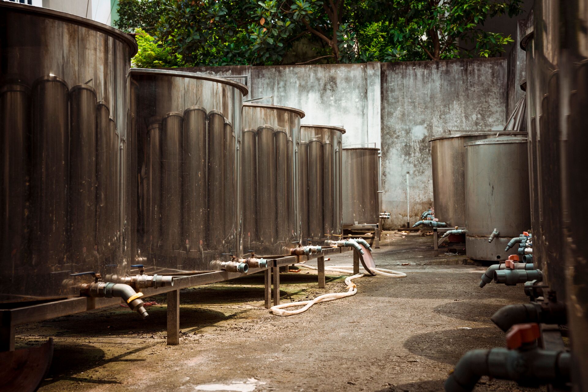
Batch systems, or kill tanks, provide thermal treatment by filling a decontamination tank, heating the contents to a setpoint, and holding for a required duration before cooling and discharge.
- Broad Compatibility: This approach is geared for the entire gamut of waste streams, from low-solids biopharmaceutical research to extremely high-solids BSL-3Ag and agricultural research.
- Robust Operation: Batch processing is less sensitive and requires less “fine-tuned tweaking” of flow rates and heat transfers than continuous systems.
- Space and Energy: These systems usually require a larger footprint and are less energy-efficient, even when equipped with heat recovery loops.
Minimizing Labor: “Process-Through” vs. Filtration
Solids handling often creates hidden labor costs. While the first line of defense should always be robust facility SOPs to prevent debris from entering the drain, equipment design must handle the realities of daily operation. Many designs place filtration upstream to protect pumps and valves, but this approach generates contaminated solids that staff must manually handle, package, and treat separately.
A more efficient strategy is the “pass-through” approach. This design allows solids to enter the system and travel through the treatment path first. Once decontaminated, the sterile solids are safely discharged to the sanitary sewer along with the liquid effluent. This method significantly reduces manual handling and minimizes exposure risks for facility personnel.
Filtration still has a role in specific high-volume contexts. For sites with persistently high levels of solids, automated self-cleaning strainers can protect sensitive equipment and reduce downstream labor by replacing daily manual cleanouts with weekly or monthly bin maintenance.
Energy Optimization: Heat Recovery Loops
Thermal decontamination systems can consume substantial energy, especially at larger scales. Implementing closed-loop processing with a heat recovery loop improves the operating cost profile by transferring thermal energy from the hot, treated effluent to the cold, incoming influent.
This energy exchange reduces the external heat required, directly lowering utility costs, while cooling the discharge stream to protect facility piping and satisfy strict containment-level discharge constraints.
While heat recovery is possible for smaller units, typically those processing 1,000 gallons or less per day, the return on investment is highest for large-scale systems processing hundreds of thousands of gallons per day, where energy intensity is most significant.
Redundancy and Reliability
Redundancy requirements vary by a facility’s risk profile and regulatory standards. While biosafety levels (BSL) influence this, such as the differing requirements between BSL-3 and BSL-4 labs, the specific agents handled and the consequences of a release are critical factors. Some sites demand no single point of failure across key functions, while others utilize limited redundancy paired with strict alarms and interlocks.
A practical approach aligns redundancy with hazard assessments, owner expectations, and the cost of downtime, while always engineering for a baseline of maximum uptime. For example, a BSL-4 facility may require dual parallel batch systems with automatic switchover, while a lower-risk facility may rely on alarm-based intervention.
Using non-proprietary components ensures that replacement parts can be sourced locally and competitively, rather than relying on a single vendor. This strategy ensures facility continuity and higher overall responsiveness.
Design for the Human Element: Accessibility and Ease of Use
Human factors often determine a system’s real-world uptime; equipment requiring a thick manual for daily operation is impractical for a busy facility. Brandon notes that “accessibility… [and] ease of use” are critical for long-term operational success.
The goal is to provide a “one to two button operation” where an operator enters a few variables and walks away. This intuitive design utilizes intelligent interfaces that provide clear prompts, such as alerting staff when the system needs grease or specific maintenance.
Physical access is equally vital; technicians must be able to see, reach, and service components easily. Thoughtful layout and proper clearances for tools are essential, as a component that cannot be reached will not be maintained.
Achieving this accessibility requires careful engineering integration, especially in complex retrofits, where the design must balance ideal maintenance clearances with the realities of existing lab-integrated or building-integrated spaces.
The Retrofit Reality: Working Within Existing Walls
Retrofit projects present unique challenges, as existing rooms often lack adequate clearance, floor drains, or the necessary utility capacity. It is critical to determine if a facility has the infrastructure required to support operations; as Brandon notes, “Most of the time, they don’t,” necessitating additional facility improvements.
Retrofit design often involves “working backwards”. Engineers start by defining the throughput and treatment targets the facility must meet. Next, they map the real-world constraints of the space, utilities, and discharge constraints to see what can realistically fit.
Finally, they select a custom-engineered system configuration, often choosing between lab-integrated or building-integrated architectures—that balances performance needs with physical limitations.
From Checklist to Implementation
Successful deployment requires a design that reflects your facility’s true operational reality, accounting for waste characterization, peak flow, and chemical compatibility from the start. This foundation ensures that your equipment isn’t treated as a mere afterthought, but rather fulfills its role as a binary requirement for certification while acting as a reliable asset integrated with your daily SOPs and maintenance access.
BioSAFE Engineering designs and builds the technology to move your facility from policy to practice, see our case studies. Whether you are optimizing energy through closed-loop processing and heat recovery or ensuring BSL-3 and BSL-4 certification, we provide custom-engineered, robust systems built for long-term operational excellence.
Contact us today to identify near-term wins and deploy a reliable effluent decontamination system custom-engineered to your facility’s throughput, regulatory requirements, and energy needs.
Frequently Asked Questions About Effluent Decontamination Systems
What are the primary effluent treatment requirements for research laboratories?
Facilities handling biologically hazardous material must meet strict regulatory standards to ensure no harmful pathogens reach the municipal wastewater system. Requirements depend on the facility’s specific containment level.
High-containment facilities operating at BSL-3 or BSL-4 often require a dedicated effluent decontamination system before wastewater leaves the facility.
How does thermal treatment destroy harmful pathogens in liquid waste?
Thermal treatment works by heating liquid waste to a validated temperature and holding it there for a sufficient duration to achieve full inactivation. This heat-based process is verifiable and documentable, providing robust inactivation of challenging contaminants—such as prions, foot-and-mouth virus, or biological warfare agents—which is why it satisfies the strict containment-level discharge constraints regulators and sewer authorities require before treated effluent can be safely released.
What types of wastewater does an EDS typically manage?
Common sources include laboratory sinks, floor drains, equipment drains, and vivarium or procedure room washdown. In BSL-3Ag and agricultural research settings, washdown streams can carry solids such as bedding, feces, and foreign objects, which is why the thermal treatment system must be custom-engineered to facility throughput, regulatory requirements, and energy needs, rather than sized to a generic standard.
What design features define a reliable effluent decontamination system?
According to Brandon Ross, Engineering Manager at BioSAFE Engineering, reliability starts with matching the thermal treatment configuration to the facility’s actual waste stream from the outset. Beyond treatment design, key features include built-in redundancy scaled to containment requirements, intuitive controls that provide a ‘one to two button operation’ to minimize operator interaction, accessible component layouts that support long-term maintenance, and non-proprietary parts that can be sourced locally to avoid costly delays.
What is the difference between continuous flow and batch thermal treatment, and how do I choose?
Both approaches deliver effective thermal treatment, but they suit different facility profiles. Continuous flow systems—often called ‘flow-through heating’—process liquid as it enters the unit, offering a compact footprint and high efficiency through closed-loop processing and heat recovery, making them well suited for low-solids streams like biopharmaceutical research applications. Batch systems—or ‘cook-and-drain’ architectures—fill a tank, heat the contents to a setpoint, hold, and discharge in cycles, which makes them more tolerant of high-solids streams from BSL-3Ag environments and less sensitive to flow variability.